Monday, October 3, 2016

Canada and Flashlights

This past Summer we took a trip back up to the vacation home of my brother-in-law's family. It is not really a home but an entire island. Before they bought it many years ago it was a fishing camp. It is located up in the Georgian Bay close to the town of Killarney. They have spent every Summer going up and enjoying the utter beauty and tranquility as well as improving it as they went along. I have been up several times over the years and, in my opinion, it is one of the most beautiful places on the earth. I dearly love it there. The stunning beauty, incredible weather, pure water and star strewn night sky are hard to describe for anyone who has not been there.

A photo from the island from 2007

Part of the allure for me is that it is rustic. There is no commercial power to the island so when you are there you need to have a few critical tools with you. A pocket knife, a lighter and a flashlight are standard. You just always seem to need those with you. Since I am bit of an excessive when it comes to flashlights, this is just fine with me. I love little flashlights, and big flashlights, and ones that flash and one that do not, I love lanterns and spot lights, too. Which brings me to the point of this post.

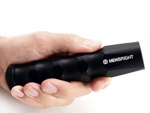
A few years ago, I recommended to my neighbor, a US Navy SEAL, that he participate in a Kickstarter program for a custom made programmable flashlight called a HexBright. He put down his money and waited a pretty long time before the product became a reality. When he received his light, I was immediately jealous, it was a very cool; solidly built, rechargeable, very bright and long lasting.


But best of all, it is programmable! It is not a simple mode and level type programming; it is fully programmable, built around an Arduino board with an on-board accelerometer and high power LED drive circuit. I have been programming micro-controllers for a very long time, so this thing was perfect for me. I wanted one of these little guys very much, but the cost was nearly $100! That is lot of money for a flashlight, but I came into some found money, I think I won a gift card at a meeting and then I took all my loose change and cashed it out and it totaled just enough to get one. It is my absolute favorite tech tools. It is heavy duty, waterproof, self-contained and works perfectly. After I received it I began working on programming it right away. I was able to take an excellent existing program called "Up and Down" and improve it. With the program I made for it, it has capabilities far beyond the reach of any normal flashlight.
Tuesday, January 12, 2016

Printed PCB for RC Telemetry Bluetooth Interface

This is an extension of the previous post.

I have been toying with the idea of putting together a control system for my smokers. It involves sensing temperatures and controlling a fan and doing some display. Pretty simple stuff for a Teensy or Arduino, but when it comes to uploading that data to the internet, those platforms fall a little short. That is where a Rasperry Pi shines. So the idea is to make a board that mounts on a Pi and is able to communicate with it, as well as do the control stuff. This is very similar to DIY controller called the "Heater Meter" (link to the store). This is going to be a very complicated board, but I thought that using the technique of leveraging a Teensy, like I do with the RC Interface would make sense. While doing the research on the Heater Meter, I found that they have their boards fabricated by OSH Park. OSH Park grew out of a club that assembled small pcb boards into a single panel and then had that made by a fabrication house. That is another story told better on their website, and not mine to tell, But the best part of it all is that OSH Park can make 3 copies of your board for $5 per square inch. That is a fantastic price and you usually only have to wait 2-4 weeks to get your board back. For my board below that ended up being about $22 or about $7.33 each. So why does this matter for the RC Telemetry Interface? Well, I figured that I needed some practice using the software that is used to create the schematic and design the board and I also wanted to see how the whole process worked, so I thought I would use the RC Telemetry Interface to learn how it all worked.

The software I used is the free version of CAD Soft Eagle, so I set out to learn it and to create the schematic and board for the interface and here are the results.

The circuit is as described in the previous post, but I added two buttons, and LCD screen and an LED. Here is the schematic.
Schematic for the RC Telemetry Interface

Pretty simple really, but the fun part is when you switch to designing the board. Even with the simple schematic shown above, the board gets pretty complex. This is the version 1.2 of the schematic and board; the boards pictured below are from the first version and there are some differences.

The picture below is the layout of the board, and what might not be apparent is that the blue lines are on the back side and the red lines are on the front. Also, all the parts are actually mounted on the front, this means that the LCD panel will mount on top of the Bluetooth module and the Teensy. I did this to protect the Teensy's program button, In the first version, I put the Teensy on the back, but the "program" button kept getting pressed when it is set on a table. This solves this problem and makes for a compact package. In addition, having the Bluetooth module on the front under the LCD allows me to see the blinking light that indicates the state of the module. You can not see it directly, but the flashing light is pretty easy to see around the LCD.

You can see that I have the two buttons positioned below the LCD and an indicator LED as well since it might be hard to see the Teensy's LED. I also placed the SPECTRA interface on the top, so it is easy to see if it is plugged in or not. Last, I have added a plug and an on/off switch that allows the unit to be powered from a LiPo battery. The plug fits the batteries available from Adafruit.

Board layout for  RC Telemetry Interface


Here are pictures (front and back) of the board that I had made from OSH Park:


And here are some pictures of the first version with the parts attached. Note, I placed the Teensy and the LCD using headers so that I could remove them for testing and debugging. Also, I made a mistake in the schematic for the Bluetooth module, getting the Rx and Tx lines not connected properly, so you can see that I had to use wires to connect it, this is fixed in the new version.


If there is interest I can post the Eagle files or point you at the projects on OSH Park's website.

Matt